PRESS
Recuperators and Glass Furnaces
An Overview
by Hugh Jenkins
Glass shops have always been high energy systems such as grain dryers and laundries and to consumers. The common early fuel was wood, and whole forests were consumed near glass furnaces. Though the fuel was cheap, the labor cost of harvesting and hauling it was relatively high. Early in the industrial revolution, energy recovery became a serious issue. The design of exhaust stacks allowed a lot of the heat to be recovered and returned to the combustion chamber, thus recouping the heat. Since then, recuperation has been the norm in industry. Early in the American studio glass recovery, energy costs were fairly low. For a few hundred dollars a month, you could run a furnace and a glory hole. The cost to melt per pound was not the issue that it was in industry. Nonetheless, by the late seventies, there was a growing interest in making more efficient furnaces, and the interest in recuperation started. The prices for fuel were not even close to what they are today, but the need to control cost was still apparent.
Early studio experiments with heat recovery were presented in the “Hot Glass Information Exchange” papers (John Bingham, 1979). Ingenious uses of radiators, Volkswagen cylinders, cast clay helixes, and double wall furnaces all worked to recover heat. Since essentially all shops were using premixed gas/ air systems, there were some inherent limits on the upper air temperatures that could be reached without pre-ignition (“popping”, backfire) occurring in the burners. During the 80’s Charlie Correll developed a sophisticated stainless alloy heat exchanger that could handle high heats and a nozzle mix system that kept the gas and air separate until in the burner throat. These were designed using blowers as the driving force and have been available on order with or without his furnace ever since; though somewhat expensive, with fuel costs going up, these became economically sound investments, saving 35-40% or more of the gas used. School programs such as Penland School of Crafts in North Carolina and Punahou High School in Honolulu installed them in 1990 and 1991. The systems returned their cost within the first eight months and lasted as much as seven years. It was not hard to convince these schools that any investment that would pay back in less than one fiscal year made good sense. The case had been made and proven for recuperators in glass studio furnaces.
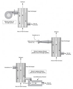
The basics of a recuperated system are an excess of recoverable waste heat, a heat exchange structure to pass the heat from the spent air to fresh air, and a means of reintroducing the heated air back into the burner. Recuperation is applicable to low temperature almost all high temperature processes such as metal smelting, ceramic firing, and of course glass melting. All recuperators need a force to move the air through the system. Tall industrial stacks create a draw that can be used in sealed furnaces to pull air through a heat exchanger such as stacked brick “checkers” and into the combustion chamber. Most smaller systems applied to kilns or studio glass furnaces use pressure from blowers. A venturi using compressed air can be used in place of a blower. In systems where the temperature approaches or exceeds the gas combustion temperature, separating the heated air from the fuel until it is in the combustion chamber, removes the possibility of pre-ignition.
Whereas the use of stacks and blowers have a history in recuperated systems, the use of venturis for this purpose has had little attention. As a way to get around fairly common power interruptions with concurrent safety system shutdowns, compressed air can be used as a driving force. The principle of venturi action is that a high pressure jet of gas entrains a much larger volume of air. If high pressure air is used through the jet, very high air flows can be achieved using relatively little compressed air. A large capacity compressed air tank can keep the system operating even through several hours of power outage. In addition, using the example of a venturi driven vacuum cleaner, the venturi can be used to pull heated air from the heat exchanger and then push it through the burner. Casting the venturi shape into a block of refractory creates a heat proof system for very high temperatures. Comparison of the operating cost of an intermittent compressor cycle to that of a continuous running blower does not indicate that compressed air used in this way is expensive.
The ideal measure of efficiency for a recuperator would be the percentage change in fuel used from before to after installation. Retrofits, though possible, are not common, since most recuperator installations are done on new equipment.
The main factors that determine the efficiency of a recuperated furnace are:
• The percentage of the waste heat actually passed through the heat exchanger.
• The surface area of the exchanger.
• The passage time of the fresh air in the exchanger.
• The conductivity of the exchanger material.
The measure of heat change in the exhaust from entry to the exit of the exchanger is also an indication of the effectiveness of the exchanger. Reductions of stack temperature from 2100° F to 700° F are being achieved today, and efforts to get higher efficiencies are being made. Changes in several factors at once can result in dramatic improvements in efficiency. In the case of the ceramic lined stack, increase of length from two feet to three feet, increase from six channels to eight, and use of a more conductive refractory improved the return from 40% to about 65%.
The issues controlling the amount of waste heat going through the recuperator are the insulation of the furnace and the fit of the door. Well built furnaces recuperate much better than those with loose fitting doors and hot exterior surfaces.
The heat must go up the stack to be reclaimed by the recuperator. The surface area of the heat exchanger is a factor of the length of the air passages, the number of passages and the configuration of the surface.
Increasing the length, number, and complexity of the passages, will increase the efficiency.
Irregular surfaces will transfer heat more effectively than smooth surfaces will.
With increased length of the stack the return is based on a percentage formula. If the first foot gives a 30% return, the second foot would give a 30% recovery of the remaining 70%, or another 21%. The third foot would give a 30% return on the remaining 49%, or another 15%. Another foot would return about an additional 10% (30% of the remaining 34%).
Various materials and configurations have been used for heat exchangers. There are big differences in the durability and effectiveness of these alternatives. There is a cost to be considered in the construction or purchase of the system to determine the value of return vs. expense. Some are not too complicated to be made by the do-it-yourselfer, college prof., or studio artist. Others require precise fabrication methods.
The stack heat exchanger that has been most available is the Correll unit. It is comprised of multiple stainless steel channels with the fresh air flowing on the inside and the exhaust passing over the outside. An input manifold brings air from the blower to the passages. Stainless can handle temperatures up to 2000° F fairly well, but the exhaust can be hotter than that especially during a melt cycle. To deal with this, a section of the stack has silicon carbide slabs as the heat conductor between the exhaust and fresh air. Over the years, these have been modified with baffles to extend the life of the stainless section. With proper care they have been known to operate well for many years.
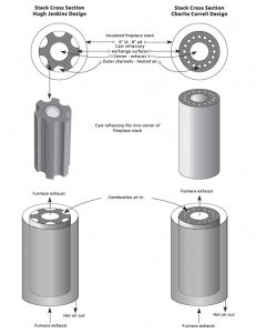
Recent development of the multiple channel, refractory-lined stack by the author has shown that a technically simpler fabrication can have excellent results (see pg. 181). Using standard insulated wood stove stack pipe, a series of passages are cast around a central exhaust channel. A higher number of channels and denser refractory has improved the response of these stacks. The first one that was made in 1997 has no apparent damage and has been used many times while other stacks were in the making for new installations.
More stack would always seem to be better, but there are diminishing returns. Theoretically you can recover close to 100% of the heat with enough stack surface. Heat flows from hot to cold, so there must always be at least a small heat differential between exhaust and fresh air entry temperature. It might be best to consider another use for the remaining heat, such as heating water, when the stack temperature is reduced to a few hundred degrees. The best stack temperature that has been directly observed is 700° F, so there is still heat available. A three foot refractory stack gets heavy and cumbersome. Adding another foot would make the stack difficult to handle. Combining the refractory stack with a lighter metal section for the lower temperatures is an area to be explored to approach optimum returns.
Most of the work with recuperators has been concentrated on furnaces. Since they are on full time, furnaces are usually the main energy consumer in the shop. Glory holes, however, can use as much or more gas in a work day than a recuperated furnace. A large glory hole uses over two gallons of propane per hour. There is a lot of room to improve the fuel efficiency in glory holes. The initial retrofit of a glory hole with a refractory stack is presented in the comparison chart with a 35% to 40% reduction in fuel consumption. A side benefit is a much cooler studio. The fact that glory holes operate with some degree of door opening almost all the time means that some heat will never be available for recovery. Still, well-fitting door faces and well-insulated walls create a much better situation for installing a recuperator. Ribbon burners are becoming a popular choice for glory holes because the heat distribution is favorable compared to spot heating for many types of work. Development of a long profile recuperated burner for glory holes would make this more attractive for many studios.
The Basic Principal of Recuperation

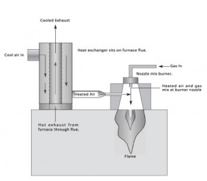
The basics of a recuperated system are an excess of recoverable waste heat, a heat exchange structure to pass the heat from the spent air to fresh air, and a means of reintroducing the heated air back into the burner. The less energy needed to heat the combustion air amounts to more energy saved.
The above diagram depicts a basic recuperator system. The heated air is introduced into the burner system at the nozzle where it mixes with the gas and ignites.
Three Ways to Power Recuperators

Two Stack Designs


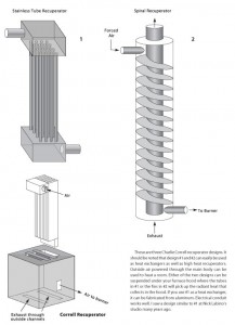
These are three Charlie Correll recuperator designs. It should be noted that design #1 and #2 can easily be used as heat exchangers as well as high heat recuperators. Outside air powered through the main body can be used to heat a room. Either of the two designs can be suspended under your furnace hood where the tubes in #1 or the fins in #2 will pick up the radiant heat that collects in the hood. If you use #1 as a heat exchanger, it can be fabricated from aluminum. Electrical conduit works well. I saw a design similar to #1 at Nick Labino’s studio many years ago.
Comparison of Installed Refractory Stack Recuperators for Propane Burners
By Hugh Jenkins
The following table shows the jets, gas pressure, and propane consumption for several recuperator installations. Two comparisons are for pre and post retrofit. The others are for similar capacity furnaces. In comparing different furnaces, some caution is advised. Older furnaces always show a change in fuel consumption. More significantly, regular, over-the-counter pressure gauges are not very accurate. At low gas pressures, a pound or two of inaccuracy can be significant. When possible, the fuel consumption should be determined by using a dedicated tank or calibrated flow meter. Otherwise, use a standard industry chart of orifices and pressures to estimate fuel flows.
Operation and Maintenance of Recuperators
In the operation of recuperated furnaces, there are a few things that are different from a straight gas/air burner. Recuperated furnaces have what is referred to as a “flywheel effect.” Once they get hot they tend to stay that way since the exhaust heat is recycled rather than lost. Also, once they get cold, they are a bit stubborn to heat back up. This is because the “new energy” supplied by fuel is only a percentage of the heat passing through the burner. If the recuperator is cool, then the heated air is also cooler. It takes a strong fuel boost to recover from a major “cool down.” Once the stack is heated up again, the recuperation increases and recovery accelerates.
Another result of recuperation is that as the furnace heats up during a melt, the recycled heat increases, and the fresh air is more expanded than at idle setting. Since this is a dynamic change, the more the furnace is heated the more the air is expanded. The result is that the flame gets less oxygen and may go over into reduction. Discovery of an air setting that will compensate for this thinning of the air, or regular adjusting of the air over the last few hours of the high melt, is necessary.
It isn’t realistic to think that once installed, re- cuperated furnaces need no maintenance. Main- tenance is minimal but necessary. Small jets are subject to interference by condensation, dust, and entrained pipe residue. The stack itself condenses the evaporated batch components. These can re- duce the efficiency of the system. As recuperators become even more efficient, they use less fuel and less air, and the jet sizes are proportionately smaller. As the stacks work to regain more of the heat, more evaporated material will condense. Fortunately, the furnace response is a good reminder of the need for maintenance. Cleaning the jets is a necessary routine in all high pressure gas furnaces. Natural gas jets are considerably larger and not so easily disrupted. Regular blowing out of the stack takes only a few minutes before charging. It is well worth it.
Another area that needs emphasis is protection of any metal parts. Over the years the Correll stacks have had widely variable life spans from six months to seven or more years. This is primarily due to method of operation. At the end of the high heat phase of melting, the exhaust exiting the furnace could be 2400° F or higher. Reducing the air flow at this point leaves the heat exchanger quite vulnerable. Continuous excess air setting is one method prescribed to counteract overheating the exchanger. Forcing a shorter melt cycle with high burner settings may be necessary for certain shop work schedules but has a negative impact on the life of the heat exchanger. A few more days of work per month may well make it worth replacing the metal unit more frequently. Under normal use with care, and cleaning, they can last a long time before warping or burning through.
In the refractory stack recuperators which use a cast refractory venturi block (pg. 180), there is a steel spud with an air jet in the hot air stream. The constant flow of cool air through these parts keeps them from being damaged. Once again it is at the end of the melting cycle when the gas and air are turned down that these parts can get hot. That is when the exhaust is hottest. Regulating the gas and air separately helps to reduce this. To protect the system and to help it cool down, the gas can be reduced to below idle pressure, but the air flow kept at a raised level for a few hours. For example, melt with the gas at 18 psi and the air jet at 32 psi. At turndown, lower the gas to 3 psi and the air to 15 psi. The idle setting when the glass has cooled is gas 5 psi and air 8 psi. The spud and jet are inexpensive parts and easily replaced, but with care, that is not necessary more than once a year.
In general, operating a recuperated furnace is no more complicated than any other gas furnace. Understanding that the gas and air volumes are greatly reduced from non-recuperated systems is the main shift. Charging cycles can be adjusted by using more or less fuel. Filling a free-standing pot in eight charges, melting for 8 hours and cooling to gathering temperature over 4 to 5 hours is a normal schedule. Safety systems and automatic controls are applicable as required or desired.
Conclusion
Recent experience indicates that there is a great savings to be gained from recuperating any gas-fired furnace or glory hole. Further experiments should lead to even higher percentage returns. The cost of installation can be returned in a few months, and the savings continue for years. In fact, glory holes may be the biggest future application since even electric furnace shops operate gas-fired glory holes. Adapting to different burner formats and exhaust locations keeps there from being an easy off-the-shelf solution that works for everyone. Installations have been very effective for units ranging from 30 to 300 pound capacity and there should be no limitations for larger or smaller size furnaces.
Hugh Jenkins


